Increasingly, a service provider’s ability to maintain a competitive market position will depend on its ability to offer premium WAN Ethernet services such as virtual private LAN service (VPLS). For incumbents, WAN Ethernet services are no longer considered a last-resort defense but an offensive, growth play. Revenues from traditional ATM transparent LAN services (TLS) continue to shrink owing to competitive pressures and enterprise migration to a more flexible and cost-effective carrier Ethernet virtual private network (VPN) service with far higher performance.
Knowing what they need to offer, service providers are faced with the question of how legacy ATM TLS can best be migrated to VPLS.
The answer can be found with the addition of ATM bridged interfaces to a VPLS instance, which allow new applications to be deployed for Ethernet-based services. One such application provides the means for migrating ATM-based TLS over a new VPLS-based network.
What is VPLS?
VPLS, or virtual private LAN service, is a Layer 2 multipoint VPN that allows multiple sites to be connected in a single bridged domain over a provider-managed IP/MPLS network. All customer sites in a VPLS instance appear to be on the same LAN, regardless of their locations. VPLS effectively implements closed user groups via VPLS instantiation. It dedicates a separate forwarding information base (FIB) per VPLS instance in order to achieve full customer isolation. VPLS achieves a larger network FIB capacity than traditional Ethernet switching since VPLS nodes, unlike legacy Ethernet switches, do not need to learn the MAC address of a VPLS instance in which they do not participate.
VPLS allows service providers to virtualize network resources by provisioning a dedicated pseudowire (PW) mesh and a dedicated label switched path (LSP) tunnel mesh and traffic engineering paths if required on a per-VPLS instance basis.
|
|
Finally, VPLS makes use of mature multiprotocol label switching (MPLS) and pseudowire capabilities such as tunnel and PW mesh signaling, fast protection around link and node failures with fast reroute, OAM and traffic engineering.
Migrating ATM-based TLS to VPLS
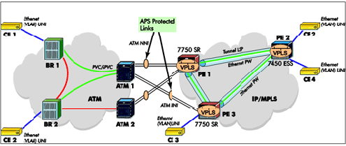
Figure 1 illustrates a TLS service provided initially over an ATM network. User sites are attached to Ethernet switches or bridges with ATM uplinks. These are referred to as BR 1 and BR 2 in Figure 1. The ATM uplink is connected to an ATM switch. The Ethernet switch ports for this user form a full or partial mesh over the ATM network. In order to avoid loops over the ATM VC mesh, the Ethernet switches participate in a Spanning Tree Protocol (STP) instance and disable forwarding over VCs that create loops for this user.
Figure 1 – Extending ATM-based TLS with a VPLS 
article page | 1 | 2 | 3 | 4 |
|
| 


